

Roller pressure is more than a maintenance figure. At the nip, pressure distribution can reveal uneven contact or misalignment. To learn how to measure roller pressure, first define the task: use readings across the nip to assess the pressure profile, or use them during maintenance to investigate contact and alignment issues.
One reading may seem enough to judge a roller setup, but the result depends on how the sensor contacts the roller. Pressure-pin height and how far a pin depresses under load can affect the recorded value. Interpret the reading in context rather than treating it as a standalone diagnosis.
This guide compares measurement approaches for testing and maintenance, then explains how to measure pressure between nip rollers, including the role of tactile sensors and pressure pins. You’ll learn what each method can show, which setup factors affect readings, and how to choose a method based on whether you need to assess pressure distribution or investigate a machine issue.
Key Takeaways
- Choose the measurement approach based on whether you’re testing pressure distribution or diagnosing a machine condition.
- Use pressure readings across the nip to spot uneven contact, and interpret them alongside roll alignment.
- Separate hydraulic system pressure from the force acting at the nip; they describe different parts of the setup.
- Account for pressure-pin height and deflection when assessing readings between nip rollers.
Primary Use: Test & Measurement, or Machine Maintenance?
Choose a measurement method based on the task: characterizing pressure distribution or investigating a machine condition. The same readings can support both, but they answer different questions.
Roller Pressure and Nip Pressure
Roller pressure describes the load applied by a roller arrangement. Nip pressure is the contact pressure where two rollers meet. It focuses on the working interface, not the force applied across the entire assembly. Keep this distinction in mind when measuring: a machine check may examine applied load, while a process test examines contact through the nip.
Nip Pressure Distribution
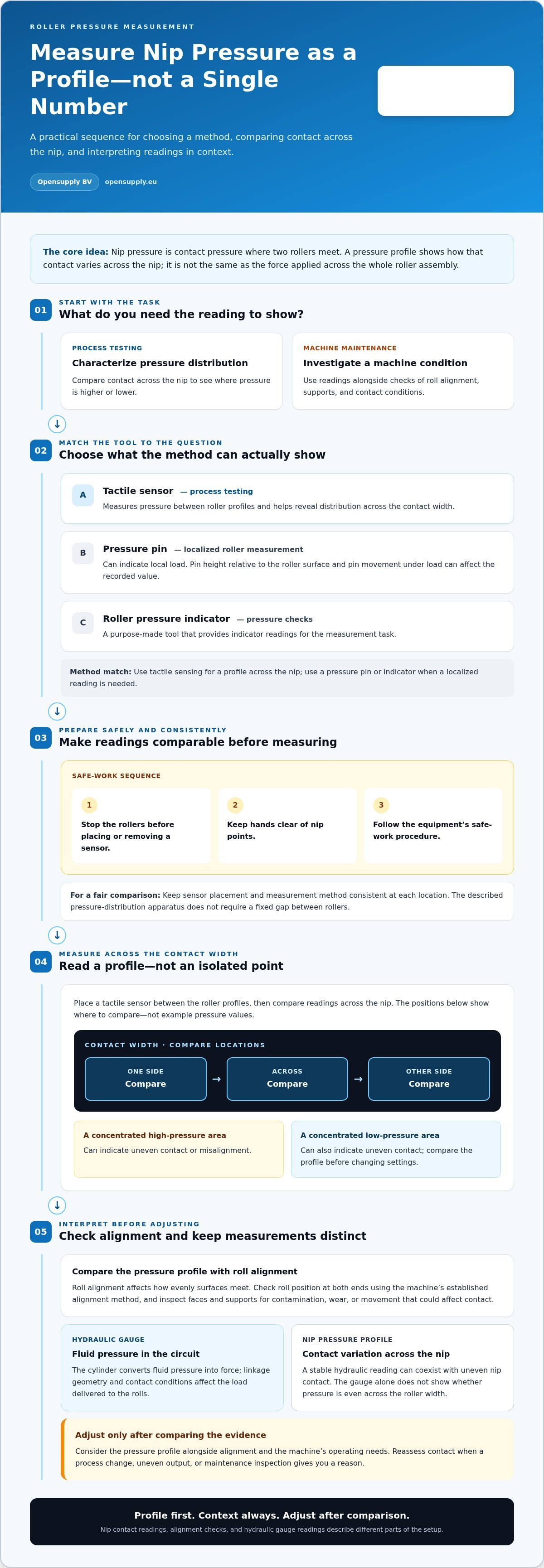
A pressure profile shows how pressure varies across the nip instead of reducing the result to a single overall reading. Place a tactile sensor between the roller profiles and assess readings across the contact width. A concentrated high- or low-pressure area can indicate uneven contact or misalignment. Compare the profile across the nip before changing settings, so one isolated reading doesn’t drive the adjustment.
Measurement Tools
Tactile sensors measure pressure between nip roller profiles and help reveal uneven distribution. Pressure pins offer another approach: their height relative to the roller surface and their movement under load can affect the recorded pressure. A roller pressure indicator is another purpose-made measurement tool. Choose a method that captures the condition you need to assess, such as contact variation across the nip.
Checking and Adjusting Pressure
When should you check pressure? Reassess contact when a process change, uneven output, or maintenance inspection gives you a reason. Adjust settings only after comparing the pressure profile with the machine’s operating needs. Stop the rollers before placing or removing a sensor, keep hands clear of nip points, and follow the equipment’s safe-work procedure.
| Option | Best for | Shows |
|---|---|---|
| Tactile sensor | Process testing | Pressure distribution |
| Pressure pin | Roller measurement | Local load, affected by pin position |
| Roller pressure indicator | Pressure checks | Indicator readings |
Use tactile sensing for a profile across the nip, and a pressure pin or indicator when the task calls for a localized reading.
The described apparatus can measure pressure distribution in roller processes without a fixed gap between the rollers. A fixed roller gap is not required for this measurement.
Roll alignment and nip uniformity
Roll alignment affects how evenly the surfaces meet across the nip. A skewed or uneven setup can produce a pressure profile that varies from one side to the other. Check alignment alongside pressure distribution rather than treating a single reading as proof that the rolls are parallel. For example, low pressure at one end may indicate uneven contact, while alignment checks can help narrow down the cause.
Start with the machine stopped and follow its safe-work procedure. Inspect the roll faces and supports for visible contamination, wear, or movement that could affect contact. Then compare the roll position at both ends using the machine’s established alignment method. Record your observations before making adjustments. This provides a baseline and helps distinguish a persistent alignment issue from pressure variation that appears only under operating load.
- Check that the roll faces are clean and free from material buildup.
- Compare the position of each roll at both ends using the equipment’s alignment references.
- Measure pressure across the nip and note where the profile changes.
- Correct the alignment or setup only after comparing the observations and readings.
A tactile pressure sensor can show whether contact is consistent across the roller profiles. Use the same placement and measurement method at each location so the readings are comparable. If one side repeatedly gives a different result, inspect alignment and support conditions before changing nip force. Interpret pressure-pin measurements carefully too: pin height and movement under load can affect the recorded value.
Guiding rollers help direct moving material through a process, but they don’t replace an alignment check on the nip rolls themselves. Keep the distinction clear when diagnosing tracking problems. If you’re reviewing roller setup, roll alignment considerations can help frame the next measurement step.
Hydraulic pressure and nip force
A hydraulic gauge measures fluid pressure in the circuit, not pressure across the roller nip. The cylinder converts fluid pressure into force, while linkage geometry and contact conditions affect the load delivered to the rolls. Keep these measurements distinct. A gauge reading describes the hydraulic system; it doesn’t show whether pressure is even across the roller width.
Nip force is the load pressing the rollers together. At the contact interface, roll alignment, surface condition, and the material passing through can affect pressure distribution. A stable hydraulic reading can coexist with uneven nip contact. If one side of the web shows a different process result, compare the hydraulic condition with a direct pressure profile before changing the system setting.
Use a consistent sequence to distinguish circuit pressure from contact pressure. Record the machine’s hydraulic reading under its normal operating condition, then measure the nip with a suitable pressure-sensing method. Keep the operating state and measurement position consistent when comparing results. Take particular care with pressure-pin readings because pin height and movement under load can affect the recorded value.
- Identify the hydraulic gauge or pressure display connected to the roller circuit.
- Record the reading and the machine condition at the time of measurement.
- Measure contact pressure across the nip, noting variations from one side to the other.
- Compare both results before adjusting hydraulic settings or roll position.
Changing hydraulic pressure to correct every uneven profile can mask the real cause. For example, low pressure at one end may result from misalignment rather than insufficient circuit pressure. Check the roll setup and contact pattern first. Change one setting at a time, then repeat the measurements at the same positions and under the same conditions. This makes the effect of each adjustment easier to identify.
Measuring pressure between nip rollers
Measure at the contact interface when you need to assess how load acts across the nip. Sensor position, pin movement, and roller temperature can all affect the result.
Pressure Measurement
A radial pressure pin mounted in one roller can transmit load from its outer end to a pressure-sensitive device inside the roller. This method measures load at the nip, including in processes without a fixed gap between rollers. Optional thermal compensation allows measurement without waiting for the rollers to cool or stabilize in temperature.
Pin movement matters. Depression under load can cause erroneous readings, so apply a correction method when interpreting the measurement. Record the sensor position and operating conditions with each result.
Pressure Calculation
Calculate average pressure by dividing the force acting at the nip by the contact area: pressure = force ÷ contact area. Use compatible units for force and area, and define the effective contact area for the roller and material being measured. This gives an average, not a map of local pressure differences.
A sensor reading measures pressure directly at its position; a calculation estimates average pressure from force and area. Use a distribution measurement when local variation matters.
What is the correct roller pressure for printing, laminating, or industrial rollers? There is no single value for every process. The required setting depends on the material, roller arrangement, and desired process result, so use the machine’s process target rather than a universal figure.
To calibrate a roller pressure gauge or load cell, follow its calibration procedure and compare its output with a suitable reference. Keep sensor placement and loading consistent, then record any correction applied. Pressure pins need particular care because pin movement under load can affect the reading.
For a reliable nip measurement, place the sensor at the intended contact point and keep the measurement conditions consistent. If the rollers run hot, thermal compensation can avoid waiting for temperature stabilization. Compare readings across relevant positions to identify differences in pressure distribution, not just one local value.
Use a pressure calculation for an average; use direct sensing to examine local nip conditions. Explore roller pressure measurement options for a practical next step.
Opensupply: Air shaft
Opensupply BV supplies air shafts for roll-handling applications and a roller pressure indicator complete set for pressure checks. Choose the indicator when you need to assess roller pressure directly; consider an air shaft when specifying roll-handling components for the same production line. These serve different equipment needs, so select each according to its role in your setup.
When translating nip readings into an equipment decision, keep the requirement clear: pressure assessment and roll handling call for different components. Opensupply BV also supplies rigid couplings KTS / KTE / KTA divided two-piece and rotary couplings for other connection requirements.
Contact Opensupply BV or visit Opensupply BV online to discuss the relevant product category.
Make the Next Measurement More Useful
Make each roller pressure check a useful reference for the next setup decision. Record the operating condition, sensor position, measurement method, and any adjustment made. This record helps distinguish a process change from a change in measurement technique and gives maintenance and production teams a shared basis for reviewing results.
When deciding how to measure roller pressure on a future run, define the question first: are you checking a process condition, investigating a fault, or comparing a setup? Match the measurement to that purpose, then keep the method consistent. This makes the result easier to interpret and more useful for the next decision.
For equipment selection related to roller measurement, contact Opensupply BV with your application details. Contact Opensupply BV about roller measurement. A clear measurement objective is a practical starting point for your next step.
Frequently Asked Questions
How is roller pressure measured?
Measure roller pressure with a suitable pressure-sensing tool, then record the machine condition and sensor position with the result. For a useful comparison, repeat the measurement with the same setup and material conditions. Keep readings from different operating states separate. This helps show whether a pressure change reflects an adjustment, a process change, or inconsistent measurement technique.
How do you measure pressure across the width of a roller?
Take readings at consistent positions from one end of the roller to the other. For example, compare the operator side, middle, and drive side, keeping sensor placement and loading consistent. Record each position separately rather than combining the readings into one average. A position-by-position record makes side-to-side trends visible and helps guide further alignment or setup checks.
What causes uneven roller pressure, and how can it be fixed?
Uneven pressure can result from roll misalignment, contamination on a contact surface, or a setup that applies load unevenly. Inspect the roller faces and supports, then address visible buildup or alignment issues before changing the applied load. Recheck the pressure profile after each adjustment. Changing one condition at a time helps show which correction affected the contact pattern.


