

Material choice can change how industrial guiding rollers handle wear, noise and impact. The right assembly also depends on load and rail fit: medium loads can use simple ball bearings, while heavily loaded rollers use roller bearings. Vulkollan polyurethane rollers have a Shore A hardness of 92°, making material properties a practical part of selection.
Roller wear is only one part of choosing industrial guiding rollers. A rail that does not match its roller can reduce support, while dirt and degraded lubricant can restrict movement and increase maintenance needs. These are common issues when keeping a guided system running reliably.
This article explains how roller construction and bearing type relate to load, and how Vulkollan compares with nylon or POM in hardness. It also covers abrasion resistance, rebound, noise and shock resistance, as well as the effects of fit, contamination and lubrication. Use these factors to select and maintain rollers for the conditions your equipment actually faces.
Key Takeaways
- Match the roller assembly to the system’s load and movement, and consider how gaps can affect support and contamination.
- Assess how surface material influences noise and shock response in the operating environment.
- Use cleaning and relubrication to limit the effects of fibres, dust and gumming lubricant on rolling performance.
- Compare roller types by their construction and material properties to narrow down a suitable option for the application.
Guide roller assembly replacement part
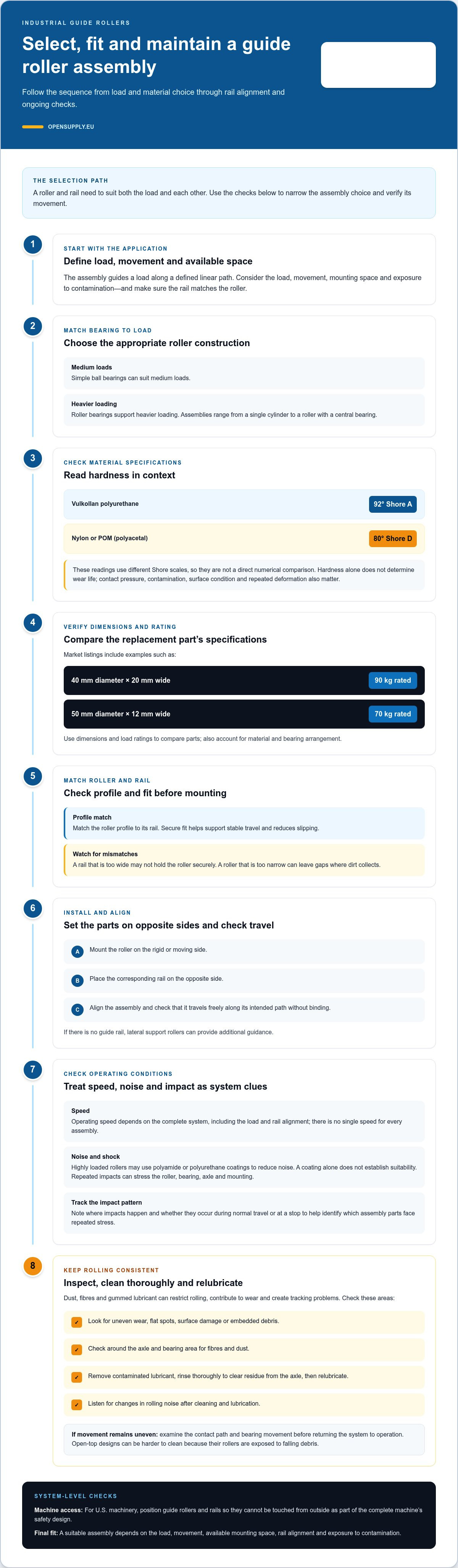
A guide roller assembly moves a load along a defined linear path. The roller and rail must suit both the load and each other.
Roller types, specifications, and costs
Assemblies range from a single cylinder to a roller with a central bearing. Ball bearings suit medium loads; roller bearings support heavier loading. Material and dimensions also affect selection. For example, market listings include rollers measuring 40 mm in diameter and 20 mm wide, rated for 90 kg, and 50 mm in diameter and 12 mm wide, rated for 70 kg. These examples show why dimensions and load ratings matter when replacing a part.
In the United States, cost depends on the required dimensions, materials, bearing arrangement and load capacity. Operating speed depends on the complete system, including the load and rail alignment. There is no single speed that applies to every assembly.
For U.S. machinery, assess roller access as part of the safety design of the complete machine. Position guide rollers and rails so they cannot be touched from outside.
Installation and alignment
Installation involves securing each roller and aligning it with its matching rail. Correct fit supports stable travel and reduces slipping. First, match the roller profile to the rail. Mount the roller on the rigid or moving side and place the corresponding rail on the opposite side. Check that the assembly travels freely along its intended path without binding.
A rail that is too wide may not hold the roller securely. A roller that is too narrow can leave gaps where dirt collects. If a system has no guide rail, lateral support rollers can provide additional guidance. For a tailored assembly, account for the load, movement, available mounting space and exposure to contamination. Together, these factors determine how the rollers guide the load along its path.
Noise, shock resistance, and maintenance
Dirt, fibres and gummed lubricant can cause wear, tracking problems or failure. These contaminants restrict rolling, while debris around an axle can interfere with smooth movement.
Noise can offer another clue about operating conditions. Highly loaded rollers may use polyamide or polyurethane coatings to reduce noise. A coating changes contact between the roller and rail, but noise reduction alone does not establish suitability. Load, movement and the operating environment still matter.
Shock resistance depends on the entire assembly. Repeated impacts stress the roller, bearing, axle and mounting. A coated roller can soften contact, while the core and bearing carry the mechanical load. Note where impacts occur and whether they happen during normal travel or at a stop. This helps identify which assembly parts face repeated stress.
Regular cleaning and relubrication help maintain consistent rolling. Fibres and dust can collect around the axle, and old lubricant can gum. A superficial wipe may leave particles behind, so rinse the assembly thoroughly and remove residue from the axle. Open-top designs can be harder to clean because the rollers remain exposed to falling debris.
- Inspect the roller surface for uneven wear or embedded debris.
- Look for fibres and dust around the axle and bearing area.
- Remove contaminated lubricant, rinse thoroughly, then relubricate.
- Listen for changes in rolling noise after cleaning and lubrication.
These checks can help distinguish drag caused by contamination from persistent noise or impact stress. If a roller still runs unevenly after cleaning, examine its contact path and bearing movement before returning the system to operation.
For replacement selection, compare application needs with the available guiding rollers. Material, load, and exposure to debris all affect the choice. A roller pressure indicator complete set can also help assess roller pressure in relevant processing setups.
Guide rollers and rails are often lubricated to improve rolling. Regular cleaning and relubrication help prevent capacity loss caused by fibres, dust and gummed lubricant. Rinse axles thoroughly rather than cleaning superficially, so dirt particles are removed.
Abrasion resistance and rebound
Abrasion resistance describes how well a roller surface withstands material loss during contact. Rebound describes how quickly a resilient material recovers after deformation. These properties affect roller performance in different ways. A hard surface may resist indentation, but hardness alone does not determine wear life. Contact pressure, contamination, surface condition and repeated deformation also matter. In a web-handling system, assess the actual contact path rather than choosing by hardness alone.
Vulkollan polyurethane guiding rollers have a Shore A hardness of 92°. Nylon or POM, also called polyacetal, rollers have a Shore D hardness of 80°. These readings use different Shore scales, so they aren’t a direct numerical comparison. Use the values to identify material specifications, then consider the operating conditions. Fibres or dust at the contact surface can act as abrasive particles, changing wear patterns even when roller material remains unchanged.
Rebound matters when a roller deforms under load or impact. A resilient tread can recover after contact, while a less resilient surface may retain deformation. The effect depends on the material and operating conditions. Consider whether the roller faces repeated impacts, steady contact or changing loads. Then check whether the surface returns to its working shape and maintains stable contact. These observations help distinguish temporary deformation from progressive wear.
For a practical comparison, inspect each roller for uneven wear, flat spots, surface damage and embedded debris. Record the material, Shore hardness and wear location. Compare rollers under similar loads and contact conditions, since a side-by-side comparison is more useful than hardness alone. Steel cores provide strength to carry the required forces despite compact roller dimensions. The tread and core therefore have different roles in the assembly. For industrial guiding rollers, match the tread’s wear and rebound properties to its contact conditions, while accounting for the supporting core.
What types of industrial guide rollers are available?
Industrial guide rollers vary in construction, bearing and contact material. These choices determine how an assembly supports a load and follows its guide path.
Construction ranges from a simple, one-piece cylinder to a larger roller with a bearing at its centre. In a compact cylinder, the roller and body form one piece. A multi-part design separates the rolling surface from the central bearing assembly, giving each part a distinct mechanical role. The required load helps determine which arrangement fits.
Bearing type is another key distinction. Simple ball bearings can provide rolling capacity for medium loads, while heavily loaded rollers use roller bearings. The bearing carries the rolling load, while the roller’s outside surface contacts the guide system. Considering the bearing separately from the surface material helps clarify each part’s function.
Contact materials include Vulkollan polyurethane, nylon, and POM, also called polyacetal. Vulkollan rollers have a Shore A hardness of 92°. Nylon or POM rollers have a Shore D hardness of 80°. These measurements use different Shore scales, so compare each value within its own scale. High-strength steel can form the load-carrying core, while a polymer tread provides the contact surface.
Other configurations address noise or support needs. Polyamide or polyurethane coatings can reduce noise on highly loaded rollers. If a guide rail is unavailable, lateral support rollers can supplement the system. The right arrangement depends on how the roller meets the load and guides movement.
- Choose monolithic or multi-part construction based on assembly needs.
- Match ball or roller bearings to the load category.
- Compare tread material, core construction, and contact conditions.
- Consider lateral support when the design lacks a guide rail.
Review roller configurations for your application to compare guiding options with your system’s requirements.
Opensupply: Air shaft
Opensupply BV supplies air shafts and guiding rollers for processing-industry equipment. Turn to Opensupply BV when selecting components for a web-handling setup or reviewing related parts in the same assembly. Roller pressure indicators help assess roller pressure, while rotary couplings and divided two-piece rigid couplings KTS / KTE / KTA serve other equipment requirements.
Component selection depends on the machine layout and the role of each part. Identify the operating conditions, mounting arrangement and relevant interfaces before comparing options. This keeps the decision focused on the equipment’s actual needs rather than treating every component as interchangeable.
Contact Opensupply BV to discuss components for your application.
Make the next roller decision more precise
Before specifying industrial guiding rollers for a new or revised setup, define the key operating conditions. Record the web path, mounting constraints, expected contact and signs of wear during operation. This provides a practical basis for comparing replacement options and keeping component choices consistent as equipment changes.
Use this reference when reviewing the wider assembly. A roller choice may affect how adjacent equipment connects and functions, so consider the interfaces as well as the roller itself. Opensupply BV supplies processing-equipment components, including air shafts, rotary couplings and divided two-piece rigid couplings KTS / KTE / KTA.
If you are planning a replacement or evaluating a web-handling assembly, share the application details with Opensupply BV and discuss the relevant components. A clear description of the equipment and operating conditions provides a useful starting point.
Contact Opensupply BV to discuss roller needs and identify a practical next step for your setup.
Frequently Asked Questions
What are industrial guiding rollers and how do they work?
Industrial guiding rollers control lateral movement by rolling along a track or guiding surface. In web handling, they help keep a moving web aligned as it passes through equipment. For example, a roller beside the web path can guide the material without driving it. Its role is guidance, so the surrounding machine determines its placement and movement.
What materials and coatings are used for industrial guiding rollers?
Common options include polyurethane, nylon, POM and steel components. Some assemblies combine a steel core with a polymer tread, separating structural support from the contact surface. Choose the coating according to contact conditions and operating priorities. For example, a coating may reduce noise under heavy loading, while the supporting core carries the assembly’s forces.
How do I choose the right guide roller for a conveyor or production line?
Start by assessing the machine’s load, travel path, mounting space and contact conditions. Compare the roller profile with the guiding surface, and consider exposure to dust or fibres. A roller installed above a conveyor may face falling debris, while one beside a clean web path may encounter different wear conditions. These details help narrow down suitable construction and materials.
How should industrial guide rollers be maintained and lubricated?
Keep the axle and rolling surfaces free of trapped debris, and use lubricant suited to the assembly. During inspection, note changes in noise, rolling smoothness and wear location. For example, debris concentrated near one axle may indicate a cleaning issue, while uneven surface wear can point to inconsistent contact. Remove contaminated lubricant, rinse the axle area and relubricate.
What safety standards or regulations apply to industrial guiding rollers in the United States?
For U.S. machinery, assess roller access as part of the complete machine’s safety design. Position guide rollers and rails so they cannot be touched from outside.


