

Air can support a moving load without being the mechanism that stops it. A pneumatic safety bearing uses a pressurized air film to support and guide equipment with low contact friction. Holding or stopping the load may also require valves that block airflow to actuators, or a mechanical brake or lock. In one described solar-panel system, an air bearing supports an average holding force of 600 N.
It’s easy to treat support, holding and stopping as one function, but each depends on a different part of the system. This article explains how air bearings create a supporting film, how pneumatic systems block movement, and when a mechanical brake or lock may be needed. It also covers the design factors behind bearing arrangements, load capacity, speed and air pressure, helping you understand how these elements work together in equipment.
Key Takeaways
- Separate load support from stopping: the air film carries and guides a load, while valves or mechanical restraints control movement.
- Match the bearing arrangement to the application. Design choices affect how the system supports and guides equipment.
- Assess load, speed, and air supply together. The operating requirements determine which specifications matter most.
- Compare air, conventional, and magnetic bearings by how each supports and controls motion, then weigh those differences against the equipment’s needs.
Holding, blocking, and stopping equipment
An air bearing supports and guides a load on a pressurised film. It reduces direct contact at the bearing surface, but does not automatically lock equipment in position. A pneumatic actuator moves the load, while a valve controls airflow to the actuator. Treat support and stopping as separate functions: a pneumatic safety bearing supports movement, but should not be treated as the machine’s restraint.
To block motion, a safety valve can interrupt airflow to an actuator and prevent machine start-up. However, a suspended or externally loaded part may still move under gravity or another force. Some applications add a mechanical brake or a lock on the cylinder piston rod, particularly when high holding force or rapid stopping is needed. In a pneumatic safety bearing arrangement, the valve, actuator and restraint each have a distinct role.
Select and size a pneumatic safety bearing by assessing the load, its distribution, required travel and operating conditions. Match the bearing area and air-supply pressure to the load, then account for the equipment’s guidance needs and the separate method used to hold or stop it.
- Support: the air film carries the load and allows guided movement.
- Block: the valve interrupts actuator airflow to control pneumatic movement.
- Hold: a mechanical lock or brake restrains a load that could move under an external force.
- Stop: a brake or lock may be needed where stopping must be rapid.
Pressure loss also needs consideration. Pneumatic systems can use pressure switches to detect a drop and shut off machine power. This response can limit unexpected operation, but it does not mechanically hold a load. When selecting a pneumatic safety bearing, distinguish between fault detection, actuator blocking and restraint against movement.
Compressed air also creates a cleaning hazard. According to the Occupational Safety and Health Administration, keep compressed-air pressure below 30 psi when cleaning surfaces. This limit applies to surface cleaning, not to bearing sizing or actuator settings. Keep those functions distinct when specifying compressed air for equipment.
What types and designs of pneumatic safety bearings are available?
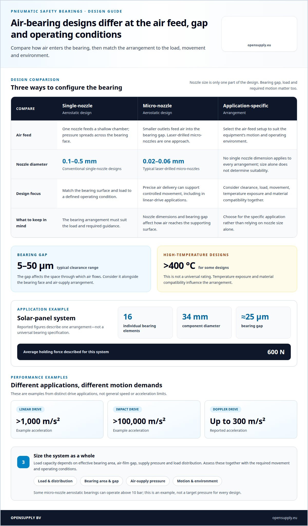
Air-bearing designs differ in how they feed and distribute pressurised air. A conventional aerostatic design uses a single nozzle to feed a shallow chamber. Pressure spreads across the bearing face and forms the supporting film. This arrangement suits applications where the bearing surface and load can be matched to a defined operating condition.
Micro-nozzle designs use smaller air outlets to control how air enters the bearing gap. Conventional single-nozzle aerostatic bearings use nozzle diameters of 0.1-0.5 mm. Laser-drilled micro-nozzles typically measure 0.02-0.06 mm in diameter. These are distinct design approaches, not interchangeable specifications: nozzle size affects air distribution, while the final arrangement must also suit the required load and movement.
The clearance between bearing surfaces is another defining feature. Typical air-bearing clearances range from 5 to 50 μm. A smaller gap changes the space through which air flows, so the bearing face, supply arrangement, and application must be considered together. In a micro-nozzle design, precise air delivery supports controlled movement, including in linear-drive applications.
Operating environment can shape the design too. Some air bearings are designed for operating temperatures above 400 °C. That figure describes designs intended for high-temperature service, not a universal rating for every bearing. Material compatibility, temperature exposure, load direction, and the required motion all influence the bearing arrangement. Operational safety and technical efficiency depend substantially on designing that arrangement for the specific application.
When comparing designs, focus on the physical setup and its function:
- Single-nozzle aerostatic: one nozzle feeds a shallow chamber beneath the bearing surface.
- Micro-nozzle aerostatic: laser-drilled outlets provide a different, smaller-scale air-feed arrangement.
- Application-specific arrangement: clearance, load, movement, and operating temperature guide the selection.
These categories describe how air is supplied and how the bearing is configured. Choose a design to match the equipment’s motion and operating environment, rather than relying on nozzle size alone.
What are the load capacity, speed, and pressure specifications of pneumatic safety bearings?
There is no single load or speed rating for every pneumatic safety bearing. Capacity depends on the bearing’s effective area, air-film gap, supply pressure, and how the load is distributed. A described solar-panel system distributes its load across 16 individual bearing elements. Its components measure 34 mm in diameter, with a bearing gap of about 25 μm. These figures describe that arrangement, not a universal specification.
Pressure must be considered alongside bearing geometry. Some micro-nozzle aerostatic bearings can operate at pressures above 10 bar. This is an example of a high-pressure air supply, not a target for every design. Nozzle dimensions and the bearing gap affect how air reaches the supporting surface. The system’s load and required movement also shape the operating point.
Speed describes a different performance demand. Examples of micro-nozzle aerostatic bearings include linear drives with accelerations above 1,000 m/s² and impact drives above 100,000 m/s². A separate high-accelerated Doppler drive reaches accelerations up to 300 m/s². These examples show that air bearings can support distinct motion profiles. They are application examples, not general speed limits.
- Load: assess the supported mass and how the arrangement distributes it across bearing elements.
- Pressure: match the supply to the bearing design and its air-feed geometry.
- Speed: distinguish steady travel from acceleration or impact movement.
For selection, evaluate load, pressure and motion as a combined operating condition. A design intended for a fast linear drive may not suit a load that needs a different type of support or movement. Bearing area and air delivery determine how the film supports equipment, while required travel and acceleration define the motion demand. Specify the complete application, not just one headline figure.
How do pneumatic safety bearings compare with conventional and magnetic bearings?
The main difference is how each design supports motion. An air bearing separates its surfaces with a pressurised film. A conventional rolling bearing carries a load through rolling elements, while a sliding bearing supports movement through contact between surfaces. A magnetic bearing uses magnetic forces to support a rotor without mechanical contact during operation. Each mechanism suits different equipment layouts and operating demands.
Air bearings need a controlled air supply and a bearing gap, so performance depends on air delivery, surface geometry and load arrangement. A conventional bearing does not create an air film; its design instead depends on its bearing elements and contact surfaces. The practical comparison is not simply friction versus no friction. It also includes the supply system, mechanical layout and movement the machine must achieve.
Magnetic bearings avoid contact during supported operation but use magnetic fields rather than compressed air. Active magnetic designs use control equipment to regulate the forces supporting the rotor. This creates different system requirements from those of an aerostatic bearing, which depends on air pressure and feed passages. Neither principle automatically provides a mechanical stop: stopping and holding remain separate design functions.
- Air bearing: supports motion through a pressurized air film; air supply and gap are key design factors.
- Conventional bearing: transfers load through rolling or sliding contact; the bearing arrangement governs support.
- Magnetic bearing: supports a rotor through magnetic forces; active designs use control equipment.
For a machine with a compressed-air system and guided movement, an air bearing may fit the operating concept. A conventional bearing may suit a design based on rolling or sliding contact, while magnetic support may suit equipment designed around magnetic forces and control. Compare the complete system, including support, motion, utilities and how the load will be held when movement stops.
Review bearing options for your application alongside the machine’s support and motion requirements.
Opensupply: Air shaft
Opensupply BV supplies air shafts for processing equipment. If your application also needs an air shaft, treat it as a separate component in the wider machine design, not as a substitute for a bearing that supports and guides a load. Matching each component to its role keeps support, movement and material-handling requirements clear.
For equipment that combines rotating components, Opensupply BV also supplies rotary couplings and rigid couplings KTS / KTE / KTA divided two-piece. A roller pressure indicator complete set is another option when pressure indication is part of the equipment requirements. These products meet different component needs, so focus on the function required by your assembly.
Contact Opensupply BV to discuss an air shaft for your equipment.
Plan the next step around the full assembly
Before finalising a pneumatic safety bearing, map how it fits into the equipment’s wider mechanical layout. The bearing is one part of the assembly, and adjacent components have their own roles. A clear component plan helps align support requirements with the machine’s movement and material handling.
Opensupply supplies air shafts, rigid couplings KTS / KTE / KTA divided two-piece, and rotary couplings for related equipment requirements. When specifying a pneumatic safety bearing, treat these as separate components in the wider assembly, not as substitutes for bearing support or load restraint.
Prepare the application details that shape component selection, such as equipment function, motion, and connection requirements. Then contact Opensupply to discuss your needs.
A well-defined assembly starts with clear roles for every part. Take the next step with your equipment requirements in view.
Frequently Asked Questions
What is a pneumatic safety bearing and how does it work?
An air bearing uses compressed air to support and guide a load. Air enters the space between bearing surfaces and forms a supporting film. In a pneumatic safety bearing assembly, the bearing’s role is distinct from the machine’s controls: it supports movement, while other components manage restraint. This distinction matters when specifying support for a moving platform or guided machine part.
What are pneumatic safety bearings used for?
Air bearings are used where equipment needs air-supported guidance during movement. A pneumatic safety bearing may suit a mechanism that must move with little direct contact between its bearing surfaces. For example, air-guided support can be used in wafer-testing equipment where a chuck needs to lift for test access. The application’s motion and support layout determine whether this bearing principle fits.
How do you install, operate, and maintain a pneumatic safety bearing?
Match the bearing area and air-supply pressure to the load, its distribution, required travel, guidance needs and operating conditions. Treat the air film as support, not restraint. Use valves to block actuator airflow and a mechanical brake or lock when external forces could move the load or rapid stopping is needed. Pressure switches can detect pressure loss and shut off machine power.
What are common pneumatic safety bearing failures and their risks?
If pressure drops, a pressure switch may shut off machine power, but it does not mechanically hold the load. A suspended or externally loaded part can still move under gravity or another force, so a brake or lock may be needed to restrain it.


