

A rotating machine still needs a reliable fluid path. Industrial rotary couplings transfer liquids or gases between stationary supply lines and rotating assemblies, allowing fluid to flow as connected equipment turns. The passage layout and sealing arrangement determine which applications a coupling can serve.
Choose a coupling based on the fluid and operating conditions, not just the machine connection. This guide explains how rotary couplings work, how single- and multi-passage designs differ, and where they are used, including in paper processing, machine tools and automation. It also covers practical selection factors such as pressure, temperature, speed and fluid compatibility, so you can identify a suitable type for your application.
Key Takeaways
- Match the coupling’s flow passages and connections to the machine layout and fluid circuit.
- Compare pressure, speed, temperature, and fluid compatibility when narrowing down suitable designs.
- Identify how hydraulic oil, water, and cooling lubricant applications place different demands on seals and flow paths.
- Explore how rotary couplings support fluid transfer across industries with rotating equipment.
- Learn how design types differ and when a rotary coupling or related shaft component may suit the application.
What is a rotary coupling?
A rotary coupling transfers fluid between stationary pipework and rotating machinery through internal passages. Common failure modes include seal leakage and bearing wear. Escaping pressurized fluid can create exposure and equipment hazards.
Flow Passages and Connection Size
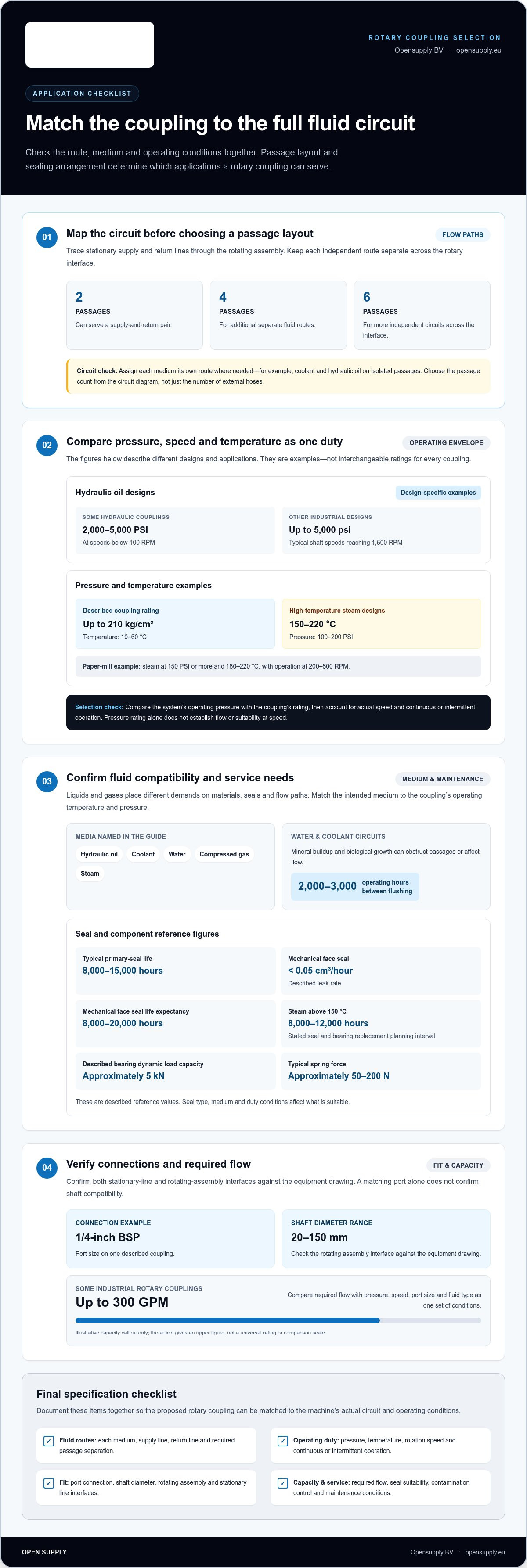
Passage count determines how many separate fluid circuits can cross the rotating interface. Designs with 2, 4, or 6 passages can keep different supplies or return lines apart. Match the passage layout to the machine’s circuit diagram, including any required inlet and outlet paths.
Connection size also affects fit with the stationary line and rotating assembly. One described coupling uses a 1/4-inch BSP port, while shaft diameters can range from 20 mm to 150 mm. Confirm both interfaces against the equipment drawing; a matching port alone doesn’t establish shaft compatibility.
Pressure and Speed Requirements
Pressure and rotation speed work together to define operating demands. Some hydraulic rotary couplings transfer oil at 2,000-5,000 PSI and below 100 RPM. Other industrial designs are described for pressures up to 5,000 psi, with typical shaft speeds reaching 1,500 RPM. These figures apply to different designs, not one universal rating.
For pressurized oil transfer, compare the system’s operating pressure with the coupling’s rated pressure. Account for actual rotation speed and whether the assembly runs continuously or intermittently. Pressure rating alone does not show whether a coupling suits a fast-running shaft or provides the required flow.
Pressure and Temperature Capabilities
Pressure and temperature ratings must fit the same operating condition. One described coupling has a rated pressure up to 210 kg/cm² and a temperature range of 10 to 60 °C. High-temperature steam designs are described for 150-220°C and 100-200 PSI. Don’t treat either specification as a general rating for every coupling.
Check the fluid, pressure, and temperature together. Hydraulic oil service differs from steam service, and seal materials and internal design must suit the medium. For steam above 150°C, the stated planning interval for seal and bearing replacement is 8,000 to 12,000 operating hours.
Seal performance is another selection point. A typical primary-seal life is 8,000 to 15,000 hours. For a mechanical face seal, the described leak rate is below 0.05 cm³ per hour, with a life expectancy of 8,000-20,000 hours. These ranges show why seal type and duty conditions matter.
Also consider bearing and spring loads within the assembly. A described bearing dynamic load capacity is approximately 5 kN, and a typical spring force is approximately 50-200 N. These figures help frame component requirements, but they aren’t substitutes for matching the coupling to the machine’s operating conditions.
Flow capacity completes the specification picture. Some industrial rotary couplings are described with flow rates up to 300 GPM. Compare required flow with pressure, speed, port size, and fluid type as one set of conditions. A high flow figure alone doesn’t establish suitability for a particular hydraulic circuit.
Fluid transfer between stationary and rotating components
A rotary union connects stationary fluid lines to rotating assemblies in machinery, technical equipment and automation systems. Its internal passages keep fluid routes separate as the machine turns.
Fluid and Gas Compatibility
Start with the medium. A rotary union can transfer liquids or gases, but its materials and seals must suit the specific fluid. Hydraulic oil, coolant, water and compressed gas place different demands on seals and flow paths. Match the coupling’s intended duty to the medium, operating temperature and pressure.
Contamination control matters in water and coolant circuits. Mineral buildup and biological growth can obstruct a passage or affect fluid flow. The guidance for these systems recommends flushing every 2,000-3,000 operating hours. Use the machine’s fluid circuit and service procedure to determine what the flush must clear.
Plan the flow path before choosing a connection. Identify the stationary supply and return lines, then trace each route through the rotating assembly. For example, a coolant inlet and outlet need separate paths if both cross the rotating interface. Mapping the circuit helps prevent crossed lines and clarifies the intended fluid transfer.
Passage Count and Multiple-Fluid Handling
Passage count sets how many separate fluid routes can cross the rotary interface. The described couplings have 2, 4, or 6 passages. A two-passage design can serve a supply and return pair; a machine with additional independent circuits may need more passages. Select the count from the circuit diagram, not from the number of external hoses alone.
A multi-passage assembly can carry separate media. For example, a rotating process unit might need coolant and hydraulic oil on isolated routes. Assign each medium its own passage and confirm the layout keeps the routes separate through the rotary joint. This preserves the intended circuit arrangement.
Industry conditions show why the passage design must match the application. A paper-mill rotary coupling may transfer steam at 150 psi or more and 180-220°C while operating at 200-500 RPM. Those conditions differ from a water circuit, so passage layout and fluid compatibility need application-specific consideration.
Before specifying a coupling, document each fluid, its supply and return route, and the rotating assembly’s requirements. Then compare that circuit map with available rotary coupling options to identify a suitable passage arrangement.
For a circuit that requires more than one medium, specify a rotary coupling configured for that duty. Rotary couplings for multiple fluids are available on request. Provide the documented fluid routes and separation requirements so the proposed arrangement can be matched to the circuit.
Hydraulic oil, water, and cooling lubricant applications
The fluid, pressure, temperature and rotation speed together define the coupling’s duty. Hydraulic circuits, water systems and machine-tool cooling each have different operating demands.
Application Media and Operating Requirements
For hydraulic oil, consider the required flow path between the fixed supply and rotating or swiveling installation. The coupling must suit the fluid circuit and its operating pressure. Water applications place different demands on seals and bearings, especially when the system runs below 80°C and 100 PSI.
Cooling lubricant service often involves high-speed spindles. These couplings can operate above 3,000 RPM, with an average seal life of 15,000-25,000 hours. Treat that figure as a design reference for this application, not as a universal life estimate across fluids or machines.
Air transfer is a gas application. Vacuum duty also depends on the pressure differential and the ability to maintain the required seal. Define whether the rotating assembly receives air, exhausts it or operates under vacuum. This affects the flow route and sealing requirements.
Selecting Couplings by Application
Start with the machine’s process. A hydraulic actuator may need pressurized oil across a rotating connection, while a spindle may require continuous coolant delivery at high speed. A water-based circuit may operate at lower pressure and temperature. Before comparing designs, list the fluid, flow direction, operating conditions and rotation duty.
Then match the coupling’s duty to the application’s most demanding condition. For lower-pressure, lower-temperature water applications below 80°C and 100 PSI, the stated seal and bearing replacement interval is 18,000 to 24,000 hours. This interval applies to that operating range, rather than to hydraulic oil or high-speed coolant service.
Industrial applications differ in how often a coupling rotates and how the fluid is used. A swiveling hydraulic installation needs a path that stays connected through movement. A machine-tool spindle needs coolant delivery while rotating at speed. Although both transfer fluid through a rotating interface, their operating priorities differ.
Consider the full operating cycle, not just the fluid name. Determine whether the machine starts and stops frequently, runs continuously or changes speed during production. These conditions affect the coupling’s duty and the demands on its seals and bearings.
For an application review, prepare a short specification covering the medium, pressure, temperature, speed, flow direction and duty cycle. Compare coupling designs against this list and the machine’s operating needs. Clear requirements help distinguish water service from hydraulic or cooling-lubricant applications.
Industries using rotary couplings
Rotary couplings are used wherever stationary supply lines need to feed rotating equipment. Common applications include paper production, machine tools, process machinery and automated systems.
In paper production, rotating rolls may need steam or another process fluid during operation. The coupling sits near the centre of the rotating assembly, connecting stationary pipework to the roll. This allows the roll to turn while fluid continues through the circuit. Selection depends on the medium, operating conditions and machine layout.
Machine tools use rotary connections to deliver coolant to rotating spindles or tools. The coupling must suit the spindle speed and coolant circuit, including its supply and return routes. Choose a design for the machine’s actual operating demands rather than assuming every spindle has the same requirements.
Process industries use rotating equipment for tasks such as mixing, coating and material handling. A rotary connection can carry fluid or gas into the moving assembly. Similar connections in automation support rotating or indexing equipment that needs a supply throughout its movement. The key question is what must pass through the rotating interface.
For applications in the United States, applicable standards and certifications depend on the equipment, fluid and intended use. Match the coupling to the requirements for the complete machine and its operating environment.
Materials vary according to the fluid and operating conditions. Mechanical face seals are one seal design; the appropriate materials and sealing arrangement depend on the medium, pressure and temperature the coupling must handle.
These applications show why one coupling specification cannot suit every installation. A paper-machine roll handling steam has different requirements from a machine-tool spindle delivering coolant. An automated rotating table may also need separate circuits for different fluids. Start with the machine’s function, then map its flow path and operating cycle.
Follow a practical selection sequence: identify the industry and machine, define the fluid or gas, trace each supply and return route, then compare the coupling’s operating limits with the equipment’s requirements. For a rotating roll, include the roll connection and process medium. For a spindle, specify coolant delivery and rotation speed. For an automated system, account for every circuit crossing the rotating interface.
The industry helps frame the application, but the machine’s duty determines the specification. Paper production, machine tools, process equipment and automation use rotary transfer in different ways. Documenting the fluid path and operating conditions gives engineers a clear basis for selecting a coupling that fits the installation.
What types of industrial rotary couplings are available?
Rotary couplings are grouped by passage layout, operating medium and duty. These categories narrow the options, but the design’s pressure, temperature, speed and connection dimensions must still match the machine. A steam-fed paper-machine roll and a coolant-fed spindle, for example, need different operating capabilities even though both transfer fluid across a rotating interface.
Passage configuration is one key distinction. Designs with 2, 4, or 6 passages provide separate routes through the rotating connection. A two-passage arrangement can serve a supply and return circuit. Additional passages can keep more fluid routes separate within the same assembly. Start by mapping every required inlet and outlet, then match the layout to the machine circuit.
Medium and duty also separate coupling types. Hydraulic versions transfer pressurized oil to rotating or swiveling installations. High-pressure hydraulic designs are described for 2,000-5,000 PSI and below 100 RPM. Coolant couplings for high-speed spindles can operate above 3,000 RPM. These examples show why a coupling suitable for oil transfer isn’t automatically right for spindle coolant.
Steam service calls for another operating range. Described high-temperature steam couplings operate at 150-220°C and 100-200 PSI. In paper mills, a rotary coupling may transfer steam at 150 psi or more and 180-220°C while operating at 200-500 RPM. Compare pressure, temperature, and rotation conditions together, rather than selecting by fluid name alone.
Capacity and connection style create further distinctions. Heavy-duty couplings are described with flow rates up to 300 GPM and 4-inch flanges. Other designs use smaller connections, including a described 1/4-inch BSP port. Shaft size and interface dimensions must fit the equipment. A large flow requirement doesn’t by itself determine the correct connection or coupling configuration.
Seal arrangement is another design factor. Mechanical face seals are used in rotary coupling assemblies; the described leak rate is below 0.05 cm³ per hour, with a life expectancy of 8,000-20,000 hours. That performance information applies to the stated seal design. Operating medium, pressure, temperature, and speed remain important when comparing seal arrangements.
To narrow the type, record the fluid, passage count, pressure, temperature, speed, flow requirement, and machine connection. Then compare those needs with the coupling’s intended duty. For a rotary assembly that needs multiple isolated circuits, prioritize passage layout. For steam or high-speed coolant, prioritize the operating range. Explore rotary coupling options against your application requirements.
Opensupply: Air shaft
Opensupply BV supplies air shafts for roll-handling equipment and industrial rotary couplings for transferring fluid between stationary lines and rotating machinery. These products serve different machine needs. Identify whether your application requires roll support or a fluid connection before choosing components.
For broader assembly requirements, Opensupply BV also supplies rigid couplings KTS / KTE / KTA divided two-piece and roller pressure indicator complete sets. Match the component category to the machine’s function and specification to keep the selection focused on the equipment’s needs.
Contact Opensupply BV to discuss the component that fits your application.
Plan the Next Step for Your Rotary Assembly
Use your machine’s requirements to guide the next decision. A concise specification should identify the fluid circuit, operating duty, connection arrangement and role of the rotating assembly. This provides a practical starting point and helps distinguish a rotary coupling requirement from related shaft or roll-handling needs.
Opensupply BV supplies rotary couplings, air shafts and rigid couplings KTS / KTE / KTA divided two-piece. When evaluating industrial rotary couplings, bring the application details together before choosing a component. Define what the assembly must connect and how the equipment operates. Clear requirements make it easier to identify a suitable product category.
Contact Opensupply BV about rotary couplings to discuss your application. A clear specification is a practical first step toward selecting the right component for your equipment.
Frequently Asked Questions
What is an industrial rotary coupling and how does it work?
An industrial rotary coupling carries fluid across the interface between fixed pipework and a moving machine part. Its body connects to the stationary supply, while an internal rotating element maintains the fluid path as the shaft or assembly turns. Seals limit leakage at the rotating interface. For example, a rotary drum can receive process fluid without a flexible hose winding around its axis.
What are rotary couplings used for in industrial applications?
Rotary couplings supply or return fluids in equipment that turns during operation. A rotating drum may need process fluid, while a machine spindle may require coolant during cutting. They also serve rotating or indexing assemblies that cannot connect directly to fixed piping. The practical test is whether the machine needs fluid transfer while rotating or moving.
How do you choose a rotary coupling based on media, pressure, temperature, speed, and flow rate?
Prepare a duty specification before comparing designs. Record the fluid or gas, operating pressure and temperature, shaft speed, required flow and connection arrangement. Include start-up and peak conditions, not just steady-state values. Then compare the coupling’s rated limits with the machine’s operating range. For a machine with multiple duties, assess each circuit separately because coolant and hydraulic oil may have different requirements.
How do rotary unions, rotary joints, and rotary couplings differ?
In fluid-transfer applications, these terms often describe components that carry fluid between stationary and rotating parts. Usage varies by industry and manufacturer. “Rotary union” commonly emphasizes the fluid-transfer function, while “rotary joint” may describe the same type of connection. “Rotary coupling” can also mean a mechanical shaft connection, so use the equipment drawing and product specification to establish whether fluid passes through the component.
How do you install and maintain an industrial rotary coupling?
Align the coupling with the machine shaft and connect the fluid lines without forcing the ports or loading the body sideways. Follow the component’s installation instructions and keep the passages clean during assembly. During operation, watch for seepage, residue, and unusual noise. A practical inspection interval is every 500 operating hours. For water or coolant circuits, flushing every 2,000-3,000 operating hours helps address deposits and biological growth.
What materials and seal types are used in industrial rotary couplings?
Seal materials must suit the fluid and operating conditions. Mechanical face seals are one type of sealing arrangement.


