

The right rotary coupling is selected by the fluid and operating conditions, not by temperature alone. A thermal oil rotary coupling transfers heat-transfer oil between stationary pipework and rotating equipment. Thermal oil joints typically operate at 150-300°C, so pressure, speed, flow arrangement and seal materials also matter.
That range is a starting point, not a complete specification. The coupling must match the system’s operating conditions and the way oil flows into and out of the rotating equipment. A mismatch can affect sealing and maintenance.
This guide explains how to compare operating conditions and single-flow or dual-flow arrangements, assess seal materials and common failure causes, and plan inspections and seal replacements. It also covers practical selection factors, from pressure and temperature to piping and oil circulation. Use these points to specify a coupling that suits the application and plan its maintenance.
Key Takeaways
- Match the joint to the actual medium, pressure, speed and flow arrangement, not temperature alone.
- Choose single-flow or dual-flow based on whether the rotating equipment needs one oil path or separate supply and return paths.
- Inspect thermal oil joints quarterly and treat a 2-3 year seal replacement interval as a maintenance planning reference.
- Check seals, bearings and fluid pathways for signs of wear or contamination that can contribute to leakage and failure.
- Plan piping to prevent oil stagnation and protect the coupling from impact during installation and operation.
Maintenance and seal replacement intervals
Plan thermal oil rotary coupling maintenance around operating hours, temperature and oil condition. A calendar interval alone may not reflect wear from demanding service.
A thermal oil joint serves the same basic transfer function as a standard rotary union, but its seals and housing must suit hot oil and the system’s operating conditions. Thermal oil joints typically operate at 150-300°C, so medium compatibility is central to selection and maintenance.
For US installations, applicable safety requirements depend on the complete thermal-oil system, its equipment and installation context. The coupling alone does not determine which requirements apply.
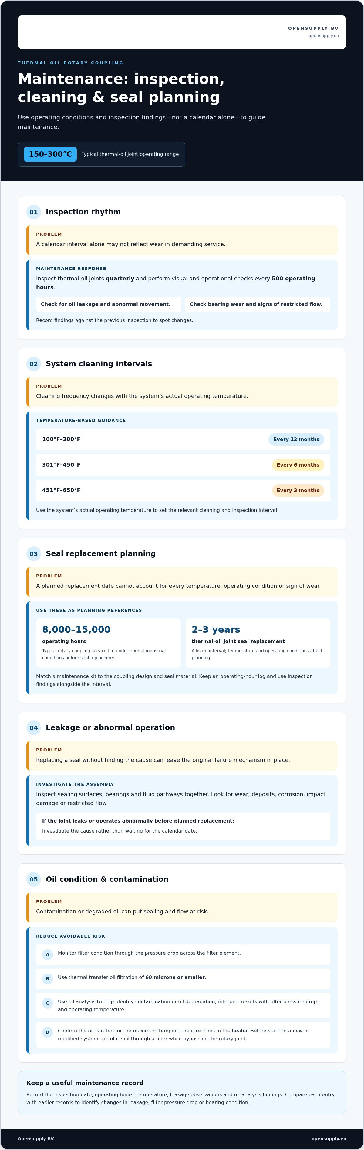
Set inspection points around both time and operating hours. Inspect thermal oil joints quarterly, and perform visual and operational checks every 500 operating hours. Look for oil leakage, abnormal movement, bearing wear and signs of restricted flow. Record findings against the previous inspection to identify changes.
Temperature also affects system cleaning frequency. Guidance recommends cleaning and inspecting thermal oil systems every 12 months at 100°F-300°F, every six months at 301°F-450°F, and every three months at 451°F-650°F. Use the system’s actual operating temperature to set the relevant interval.
Maintenance Kits and Service Life
A maintenance kit supports planned seal replacement by grouping the parts needed for the specified joint. Match the kit to the coupling design and seal material, then inspect the removed component for wear or damage. Typical rotary coupling service life under normal industrial conditions is 8,000 to 15,000 operating hours before seal replacement. Thermal oil joint seal replacement is listed at 2-3 years, but temperature and operating conditions affect maintenance planning.
Use these intervals as planning points, not as a substitute for inspection. If the joint leaks or operates abnormally before its planned replacement, investigate the cause rather than waiting for the calendar date. Keep an operating-hour log with the maintenance record to compare service life across replacement cycles.
Leak Prevention and Oil Analysis
For leak prevention, inspect sealing surfaces, bearings and fluid pathways during each scheduled check. Monitor filter condition through the pressure drop across the filter element, and use thermal transfer oil filtration of 60 microns or smaller. Oil analysis can help identify contamination or oil degradation; interpret results alongside filter pressure drop and operating temperature.
Confirm that the heat-transfer oil is rated for the maximum temperature it reaches in the heater, not just the system set point. Before starting a new or modified system, circulate oil through a filter while bypassing the rotary joint to remove contaminants. These steps help reduce contamination-related risks to sealing and flow.
Record the inspection date, operating hours, temperature, leakage observations and oil-analysis findings. Compare each entry with earlier records. Changes in leakage, filter pressure drop or bearing condition can prompt an earlier inspection and help identify whether the issue involves oil condition, contamination or joint wear.
Seal materials and failure mechanisms
A thermal oil rotary coupling depends on seal material, housing design and operating temperature. Rotary couplings can tolerate temperatures from -40°F to 400°F (-40°C to 204°C), depending on seal material and housing design. That range does not mean every design suits every thermal oil application. Compare the actual operating temperature with the coupling’s material limits.
High-temperature thermal-oil couplings used in injection molding machines often use graphite-impregnated seals. Graphite provides a sealing option for demanding heat-transfer applications, but compatibility still depends on the oil and operating conditions. For superheated steam above 200°C, silicon carbide is identified as a secondary seal material option. These materials suit different operating requirements, so don’t treat them as interchangeable.
Seal failure can develop through heat exposure, wear, contamination or poor alignment. Excessive temperature can affect sealing performance, while fluid particles can score contact surfaces. A damaged seal may cause external leakage around the joint connection. Inspect the seal faces and nearby components together. Replacing a seal without identifying the cause can leave the original failure mechanism in place.
Check the coupling as an assembly. The housing supports and contains internal parts, while seal faces control leakage between stationary and rotating sections. Bearings guide rotation, and fluid passages carry the process medium. Inspect for wear, deposits, corrosion and impact damage. Recurring leakage may point to alignment, oil cleanliness or operating conditions, not just a seal that needs replacement.
Choose corrosion-resistant materials based on the fluid and external environment. Thermal oil chemistry, moisture and cleaning agents can affect exposed surfaces in different ways. Identify which components contact the oil and which face the surrounding atmosphere, then match their materials to those conditions. No single corrosion-resistant material suits every application, and the seal material must be compatible with both the fluid and the temperature.
During inspection, compare the removed seal with an unused compatible part. Look for cracks, hardening, uneven wear, embedded particles and damage concentrated on one side. Uneven marks can indicate misalignment or uneven contact; deposits may point to contamination or degraded oil. Record the location and appearance before replacement. This helps maintenance staff compare failure patterns across machine shutdowns.
When selecting a coupling series, compare the manufacturer’s temperature limits, seal material, housing design and connections with the machine’s operating requirements. Consider startup conditions as well as steady operation, because the joint must handle the full thermal cycle. A compatible seal is only one part of the specification; the complete assembly must suit the medium and rotation requirements.
Single-flow and dual-flow configurations
Choose the flow configuration by tracing how oil enters and leaves the rotating equipment. A single-flow oil rotary joint carries one stream through its flow path, while the equipment’s return route is arranged separately. This can suit a circuit with an independent return connection. A dual-flow joint carries supply and return through the same spindle, keeping both paths within the rotating connection.
Dual flow can reduce the need for separate rotary connections where the machine requires continuous circulation. For example, one dual-flow arrangement supplies hot oil at 200°C and returns cooled oil at 90°C through the same spindle. The two streams serve different functions: one transfers heat into the rotating equipment, while the other carries oil back toward the heating circuit.
Before choosing, trace the circuit from the pump to the rotating component and back. Mark the hot-oil inlet, return outlet and joint connections. Then compare the required flow paths with the joint’s port arrangement. A single-flow setup may suit a machine with a separate return route; dual flow may suit equipment that needs supply and return through one spindle.
Flow arrangement also affects operation and troubleshooting. Record the supply and return directions, then compare temperatures at the relevant connections during operation. A change in return temperature can indicate a change in heat transfer or circulation, but does not identify the cause on its own. Check for flow restrictions, confirm pump operation and consider the machine’s heat demand together.
For a new thermal oil rotary coupling, follow the specified startup sequence before introducing oil. Guidance recommends running thermal oil rotary joints dry for at least five minutes before adding thermal transfer oil. This allows the joint to rotate before oil enters its passages. Keep the supply isolated during the dry run, then introduce oil according to the equipment’s operating procedure.
At commissioning, confirm that the spindle rotates freely and the supply and return connections match the intended circuit. Introduce oil in a controlled manner, inspect both connections for leakage and verify circulation through the rotating component. Record initial supply and return temperatures as a baseline for later checks. A clear flow diagram helps maintenance staff identify each passage during shutdowns.
When comparing rotary coupling configurations, use the circuit diagram and required supply-return paths as the starting point. Match the joint arrangement to the machine’s flow needs, then review how the installation will be started and monitored. This keeps selection focused on the actual transfer circuit rather than the coupling name alone.
Choosing a rotary joint by medium and operating conditions
Start with the process medium, then compare temperature, pressure, speed and flow arrangement. A rotary union designed for water or steam may not suit thermal oil. The joint must handle the fluid’s properties during startup, steady operation and shutdown. Specify the actual operating conditions, not just the equipment’s general application.
Thermal oil rotary joints typically operate at 150-300°C. Operating pressure is another key selection point: guidance recommends choosing a thermal oil joint when pressure is below 0.5 MPa. Pressure-seal thermal oil joints are not well suited to applications below 30 psi. Compare the operating pressure with the joint design, including the system’s pressure changes.
Steam has different demands. Industrial saturated steam rotary joints are described for 100-180°C at typical pressures of 0.1-1.0 MPa, while steam rotary joints generally operate at 0.1-1.6 MPa. Steam joints must handle pressure fluctuations and water hammer. A steam-duty joint and a thermal-oil-duty joint therefore require different selection criteria, even when both transfer heat.
Speed affects the joint’s mechanical operation. Standard rotary couplings are described as operating reliably at speeds up to 1,000 RPM, depending on their design. Treat that as a general reference, not a substitute for application-specific limits. Compare the required speed with the joint’s fluid, pressure, temperature and seal design. A rotary joint must suit the combined operating conditions.
Use a selection checklist to keep the specification precise:
- Medium: identify thermal oil, saturated steam or another process fluid.
- Temperature: record the normal and maximum operating temperatures.
- Pressure: provide operating pressure and note any fluctuations.
- Rotation: state the required speed and operating pattern.
- Flow: define whether the circuit needs single-flow or dual-flow supply and return.
Material resistance is another factor. Seal material and housing design determine temperature tolerance; graphite-impregnated seals are used in some high-temperature thermal-oil applications. The fluid and operating temperature must be compatible with the selected sealing materials. Also consider contamination and oil condition, since particles can damage sealing surfaces during operation.
Finally, compare the joint’s connections and mounting arrangement with the machine’s pipework and spindle. Thermal oil joints can be installed in any position because oil flows under pump pressure. The selection must still account for the complete circuit, including supply, return and access for inspection. A clear operating specification helps match the rotary coupling to the medium and actual duty.
How do I install and connect a thermal oil rotary coupling safely?
Use the coupling’s flow diagram and the machine’s piping layout to guide installation. Check that the ports are connected correctly, rotation is free, piping prevents oil stagnation and the joint is protected from impact. Plan each step before connecting the joint, especially after system modifications.
- Confirm the arrangement. Match the coupling’s inlet and outlet to the intended supply and return paths. For dual-flow equipment, trace both paths through the spindle and mark each connection. This prevents supply and return lines from being crossed.
- Prepare the pipework. Arrange thermal oil piping to prevent stagnant oil pockets. Check that the connection points align without forcing the joint or loading its ports. Protect the coupling from impacts and shocks, which can damage internal components or separate sealing surfaces.
- Keep passages clean. Before startup in a new or modified system, circulate thermal oil through a filter while bypassing the rotary joint. This removes contaminants before they reach the joint. Thermal transfer oil filtration for a rotary joint should be 60 microns or smaller.
- Check rotation and startup. Run the thermal oil rotary joint dry for at least five minutes before introducing thermal transfer oil. Observe the joint during rotation, then introduce oil through the planned circuit. Check the connections and joint for leakage as circulation begins.
Thermal oil joints can be installed in any position because oil flows under pump pressure. This flexibility does not remove the need for a sound pipe layout. Check for low points or dead legs where oil could stagnate, and ensure connected pipework does not place unwanted force on the joint.
During commissioning, compare the actual connections with the flow diagram. Confirm that each line serves its intended path, then record any leakage or unusual movement. If oil appears at a connection, stop and identify whether the source is the pipe joint or the rotary coupling. Avoid treating every leak as a seal failure.
Storage matters before installation, too. Keep the assembly clean, with its inlet and outlet connections sealed against contaminants. Store it on its side or on the inlet connection, not upright on the nipple. These steps help protect the flow passages and connection surfaces before the coupling enters service.
For a planned installation or replacement, explore rotary coupling options suited to the application’s flow arrangement and operating conditions.
Opensupply BV: Air shaft
Opensupply BV supplies rotary couplings for processing equipment that transfers fluids between stationary pipework and rotating machinery. Before selecting a thermal oil rotary coupling, define the medium, temperature, pressure and flow arrangement using the operating conditions described above. This provides a practical starting point for the specification.
Opensupply BV also offers air shafts, divided two-piece rigid couplings KTS / KTE / KTA, and roller pressure indicator complete sets. These products serve different equipment needs, so match the product category to the component’s function in your line. An air shaft, for example, is distinct from a rotary coupling used to transfer fluid.
For a thermal oil rotary coupling or another listed component, contact Opensupply BV or visit opensupply.eu.
Turn the specification into the next step
Before sourcing a component, turn the application details into a concise equipment specification. Include the machine interface, required flow path, operating cycle, connection layout and available maintenance access. Add any known causes of previous leakage or premature wear. This helps distinguish essential requirements from preferences and gives the selection process a practical starting point.
Treat a thermal oil rotary coupling as part of the rotating assembly, not as an isolated replacement component. Check that the proposed arrangement suits the machine’s connections and operating purpose. If the equipment layout has changed, update the specification before selecting a replacement.
Opensupply BV supplies rotary couplings, along with air shafts and divided two-piece rigid couplings KTS / KTE / KTA. For a discussion focused on rotary couplings, contact Opensupply BV about rotary couplings.
A clear specification makes the next selection step more straightforward. Start with the machine and its actual operating requirements, then select a coupling to match.
Frequently Asked Questions
What is a Rotary Coupling?
A rotary coupling transfers fluid between stationary pipework and a rotating part of a machine. Its internal passages maintain the connection while the equipment turns. For example, a heated roll can receive thermal fluid through a fixed supply line while rotating during production. The coupling’s flow arrangement depends on whether the machine needs one fluid path or separate supply and return paths.
What is a thermal oil rotary coupling and how does it work?
A thermal oil rotary coupling transfers heat-transfer oil between fixed piping and rotating equipment. The stationary side connects to the process circuit; the rotating side connects to a roll, drum or spindle. Sealing surfaces limit leakage as the parts rotate. In a dual-flow arrangement, separate internal passages carry hot oil in and cooler oil back, supporting continuous circulation through the equipment.
What temperature and pressure ratings are available for thermal oil rotary couplings?
Thermal oil rotary joints are described for typical operating temperatures of 150-300°C. Guidance recommends choosing a thermal oil joint when operating pressure is below 0.5 MPa, while pressure-seal designs are not well suited below 30 psi. These figures describe application guidance, not a universal product rating. Match the specific coupling’s limits to the machine’s operating conditions and the oil’s maximum temperature.
Which materials and seal types are suitable for thermal oil rotary couplings?
Seal selection depends on fluid compatibility, temperature and the coupling’s design. Graphite-impregnated seals are used in some high-temperature thermal-oil applications, including injection molding machines. Silicon carbide is identified as a secondary seal material option for superheated steam above 200°C. Don’t assume a material suited to steam also suits thermal oil; assess the medium and contact conditions for each seal surface.
How do I select the right thermal oil rotary coupling for a machine?
Start with the machine interface and the complete fluid circuit. For a heated roll, establish how oil enters and exits, how the connection rotates and where pipework can run. Then compare the joint’s flow design, material compatibility and operating limits with the application. Include startup and shutdown conditions in the specification, since these affect the coupling’s operating cycle as well as steady production.
How do I maintain a thermal oil rotary coupling and replace its seals?
Use inspection records to decide when a seal needs attention, rather than relying on appearance alone. Note operating hours, leakage location, rotation behaviour and any changes in oil condition. During replacement, use a seal compatible with the coupling and inspect the removed part for uneven wear or deposits. Identify the likely cause before restarting to avoid carrying the same failure mechanism into the next cycle.
What causes thermal oil rotary coupling leaks or failures?
Leaks can result from worn or damaged seals, contaminated oil, misalignment or impact damage. A leak at a pipe connection differs from seepage at the rotating seal area, so identify its source before changing parts. Deposits or scoring on a removed seal can point to contamination; uneven wear can suggest alignment or contact issues. Record the evidence to guide corrective action and future inspections.


